Designing contact force for connector pins is, honestly, a negotiation between two things that want opposite outcomes. Too little normal force and contact resistance drifts — the connection fails under vibration, fretting sets in, and nobody figures out why until a costly teardown. Too much, and insertion force climbs past whatever the assembly process can handle. Housings crack. Technicians won’t seat things properly. But getting that balance right — across temperature swings, mating cycles, and ongoing oxidation — is sort of the whole deal in connector pin contact force design.
What Is Connector Pin Contact Force Design?
Connector pin contact force design is the process of specifying and controlling the normal force a spring-loaded contact exerts on its mating surface — and the insertion force required to seat it — so electrical continuity holds across the connector’s service life. The outcome: end-of-life normal force stays above the minimum threshold for stable resistance, and peak insertion force stays below what the assembly process can handle.
Why End-of-Life Force Is the Real Constraint
Initial contact force is almost never the problem. Spring materials relax. Plating wears. Temperature cycles chew through pre-load. The number that matters isn’t day-one performance — it’s what remains after ten thousand mating cycles and years of thermal loading. So design backward from the end-of-life floor, not the initial spec. Actually — scratch that framing. Cleaner way to say it: survive the worst conditions first, then check if insertion force still fits. Because otherwise you’re going backward.
Normal Force Thresholds and What Drives Them
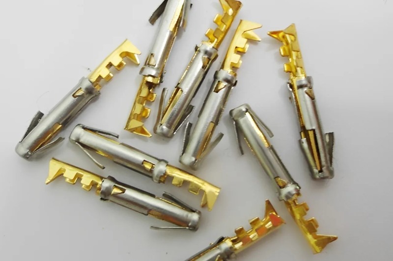
The 1 N (roughly 100 grams) minimum normal force from older connector literature traces back to 1970s standards built around tin-plated contacts. That’s a starting point… but not universal, give or take application context. Gold-plated contacts in controlled environments work reliably below 0.3 N. Yet tin in automotive underhood conditions needs more — oxide formation is basically ongoing, and you need force to break through it on every mating.
Normal Force by Application Type
| Application | Contact Type | Min. Normal Force | Key Standard |
| General signal (PCB) | Stamped spring | 0.5–1.0 N | EIA 364-38 |
| Automotive connector | BeCu or PhBr stamped | 1.0–2.5 N | USCAR-2 |
| Aerospace / mil-spec | Machined socket contact | 1.5–3.0 N | MIL-DTL-38999 |
| Medical implant | Machined BeCu pin | 0.3–0.8 N | ISO 13485 |
| Pogo pin (test / dock) | Spring-loaded plunger | 0.5–5.0 N | IEC 60512-13 |
Material Effect on Spring Force Retention
Here’s where material becomes the real variable — not geometry, not plating, but base metal stress relaxation under sustained load and temperature. Think of a contact spring as a beam held in deflection: the force depends on stress staying elastic. Stress relaxation — scratch that technical framing, basically it’s pre-load disappearing without visible damage [important: part looks fine, pre-load is gone]. C17200 beryllium copper holds force best — under 2% loss at 105°C over 100,000 hours [per published aging curves, roughly]. Phosphor bronze (C51000) loses around 40% at the same temperature. Brass is worse still.
| Material | Stress Relax. Resistance | Max Use Temp. | Typical Application |
| C17200 BeCu | Excellent (<2% at 105°C) | +125°C | Aerospace, medical, high-cycle |
| C51000 phosphor bronze | Moderate (~40% at 105°C) | +105°C | Consumer, industrial signal |
| C26000 brass | Poor (>40% at 75°C) | +75°C | Low-cycle, benign environment |
| 301 stainless | Good | +150°C | Spring-only, low conductivity OK |
The Insertion Force Tradeoff
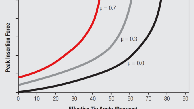
You can’t spec the highest normal force that keeps resistance stable and call it done. Insertion force is a product of normal force, friction coefficient, and how many contacts mate simultaneously. In a 50-pin connector, individual forces of 1.5 N each sum to 75 N total. That breaks latches. Causes mis-seating. That’s the deal.
How Normal Force and Friction Interact
When a pin enters a socket, the spring deflects perpendicular to insertion — that’s the normal force. Insertion force equals that multiplied by friction coefficient. Gold-on-gold runs 0.15–0.25. Tin-on-tin runs 0.3–0.5 or worse when oxidized — worse than most specs assume. So you can’t specify contact force and plating finish independently and expect predictable insertion load… that’s the stuff most drawings get wrong [verify plating friction assumptions early].
Dimensional Precision as a Force Control Mechanism
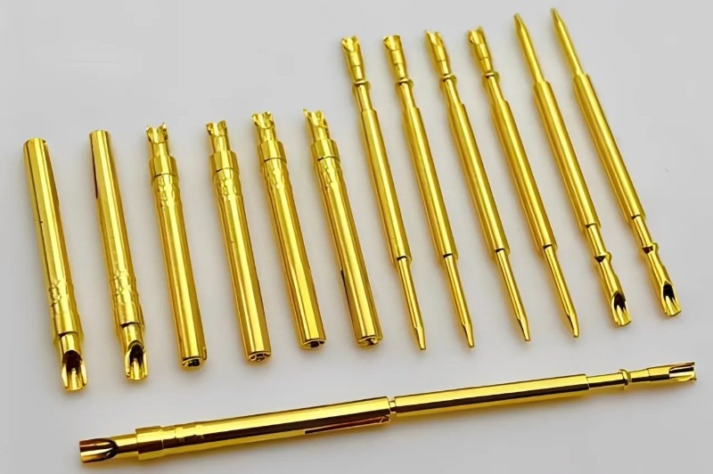
Pin diameter directly controls spring deflection — a pin 0.01 mm oversize deflects the socket spring harder, pushing normal force above spec lot-wide. Swiss-type CNC turning holds slender contact pin diameters to ±0.003–0.005 mm at aspect ratios up to 15:1 via guide bushing support; Richconn’s standard capability data covers pogo pin barrels and socket geometry. Or more plainly: lot-to-lot diameter variance breaks contact force designs — not first-article numbers.
Contact Force Design by Application Type
The tradeoff looks different depending on what the connector does. Test fixtures tolerate high insertion force — mating is controlled, tooling not hands. But a wearable medical device docked thirty times daily by a patient? Different problem entirely.
Pogo Pin Contact Systems
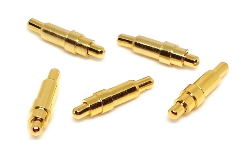
For custom-machined pogo pins and spring-loaded socket contacts used in test fixtures, medical docking stations, and wearables, spring forces typically run 0.5–3.0 N per pin. Higher force ensures oxide penetration and shock stability. Lower force reduces plating wear over millions of cycles. Yet cycle life is, honestly, sort of the real variable… not static force. A 0.7 N spring on a gold-plated contact rated for a million cycles outlasts 2.0 N that abrades through plating at 50,000 cycles and spikes resistance [check plating thickness spec before committing to force range].
Machined Socket Contacts in Mil-Spec Applications
Machined socket contacts in aerospace connectors — MIL-DTL-38999, ARINC 404 — run 1.5–3.0 N per contact because the environment demands it. Vibration at 20 G, thermal cycling from –55°C to +125°C, fretting from micro-motion. Force needs to stay above the reliability floor after all of that, give or take application margin. So the machining tolerance on socket bore diameter sets pre-load deflection — which, basically, sets the force.
When High Contact Force Isn’t the Answer
Not every reliability problem is a contact force problem. If the connector fails due to fretting corrosion, the fix is contact geometry and lubrication — not higher spring force. Higher force in a fretting scenario accelerates wear [don’t quote me, but this is consistent across application types]. Same with stress relaxation: wrong base metal for the temperature, and adding pre-load just delays the same end-state… roughly. For high-cycle consumer applications — wearables, charging contacts, test probes — gold plating at 0.5–1.0 μm combined with 0.5–1.0 N spring essentially outlasts an aggressive spring that abrades through finish by cycle 30,000. So know which failure mode you’re solving for.
Bottom Line
Contact force design isn’t a single number — it’s a range defined by end-of-life reliability on one end and peak insertion force on the other. Material choice sets how much spring force degrades over time. Plating determines the friction coefficient you’re working with. And dimensional precision on the pin and socket controls where in that range you actually land across a production lot. Or get the manufacturing accuracy wrong — and the whole contact force design is, basically, theoretical. Hmm — scratch that. More precisely: if machining variance isn’t controlled, the force spec is… sort of a fiction.
Leave a Reply